When COVID-19 reared its ugly head and sent all of humanity scurrying into our homes, a wave of makers, hobbyists, and tinkerers around the world stepped up with a variety of inventions help people stay safe. Legions of amateurs churned out ventilators, masks, sanitizer dispensers, doorknob hooks and more to help others.
One of the first pieces of advice that surfaced for those that still had to venture out into the world was simple: “Stop touching your face”. Or rather, it seems like simple advice, but in actuality is quite difficult to follow. Despite the danger, noses still need scratched, eyes rubbed, and hair teased – the human ape exists in a constant state of self-grooming.
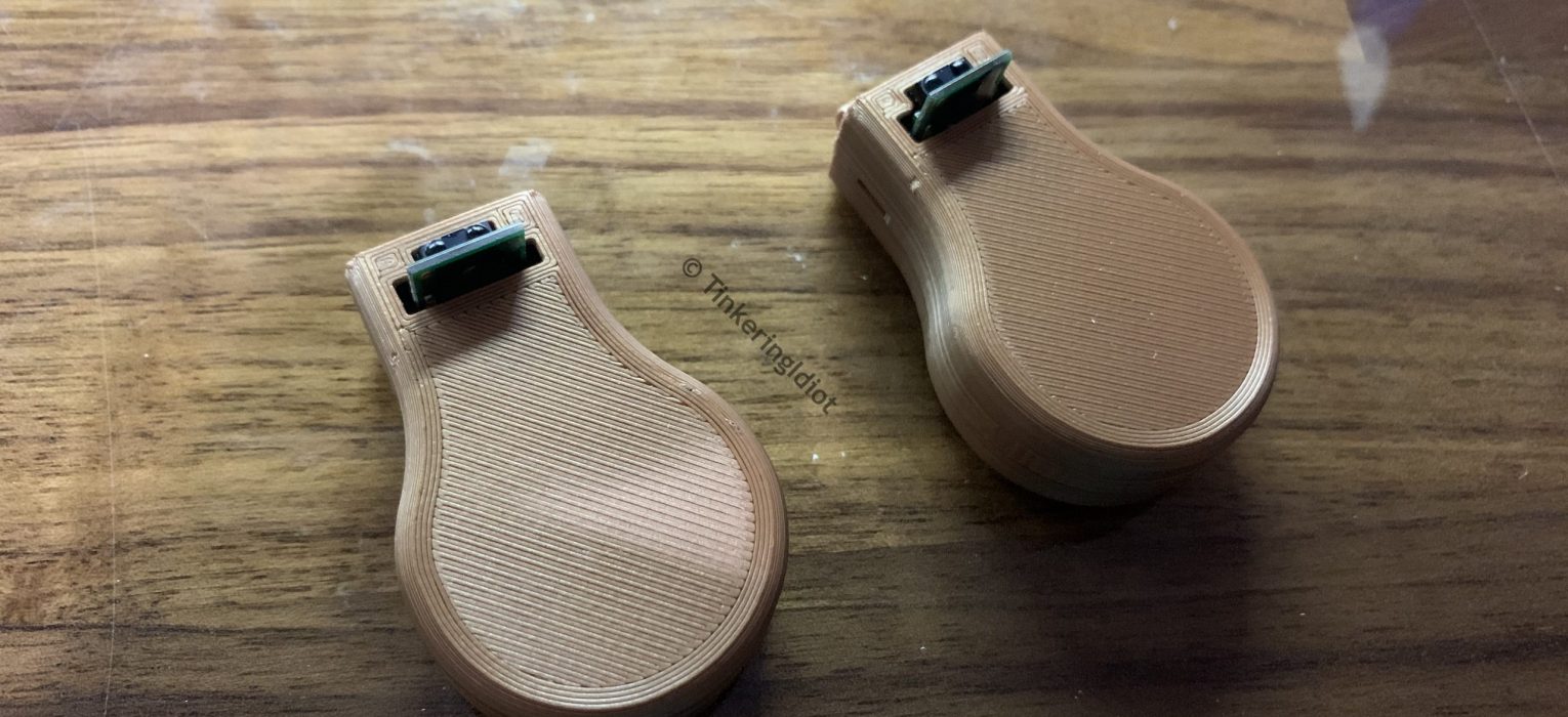
One rather notorious group of tinkerers, namely NASA’s Jet Propulsion Laboratory, devised a simple, yet elegant, solution: the PULSE necklace. PULSE is a small pendant, to be worn around the neck, with an infrared sensor and a small vibrating motor. When something warm, like a hand, approaches, the pendant vibrates to remind the wearer that face-touching isn’t safe. As I said, it’s a reasonably simple device, but quite effective. And, best of all, the fine folks at JPL released their design for free.
Materials
JPL has a full list of materials here. I haven’t got my own 3D printer, so I had local artist Little Bits of Interesting print out a few from the STL files on JPL’s Github. A few bits of wire round out the materials list, and I’m just using what I’ve got laying around.

The Build
Usually, my electronics work involves through-hole PCBs, or “fixing” children’s toys to make their irritating noises more quietly. I rarely work with tiny electronics like this, so prepare for ugly soldering.
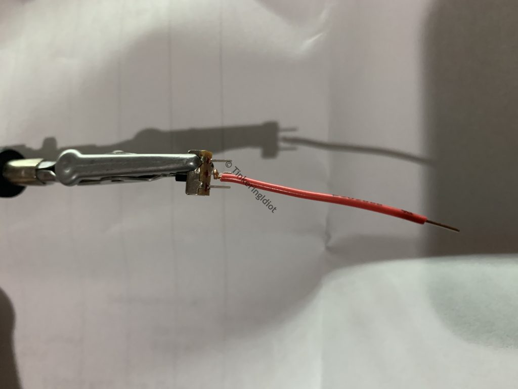
I start by soldering the longer red wire to the center post of the switch. I crimp the wire around the post to hold it in place while I solder, and this seems to result in a reasonably strong joint. I use this technique pretty much everywhere in this build.
Next I attach a shorter red wire to one of the outer posts on the switch. It doesn’t matter which. After soldering, I clip the other post off.

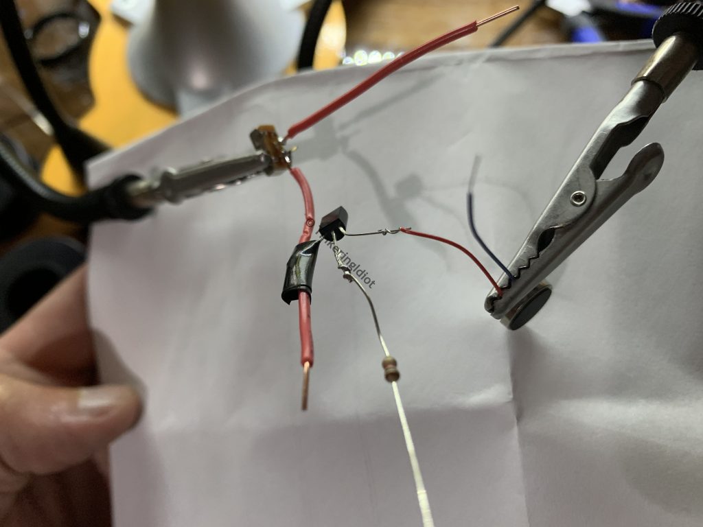
To that short red wire, I attach another short red wire, along with the emitter pin on the transistor. Using the 2N3906, the emitter is the left-most pin when viewing the flat face. I wrap the emitter pin around the two wires to hold them in place for soldering.

This mess gets soldered and wrapped in electrical tape. If I had heat-shrink tubing small enough to use here, I would.
Next, the resistor goes on the transistor’s base pin (the one in the middle).

The motor’s red wire gets soldered to the transistor’s collector pin. My wire stripper is far too large for these tiny wires, but I was able to make do with a small knife.
The short red wire goes in to the IR receiver’s VDD pin. It’s the one right next to the square GND.
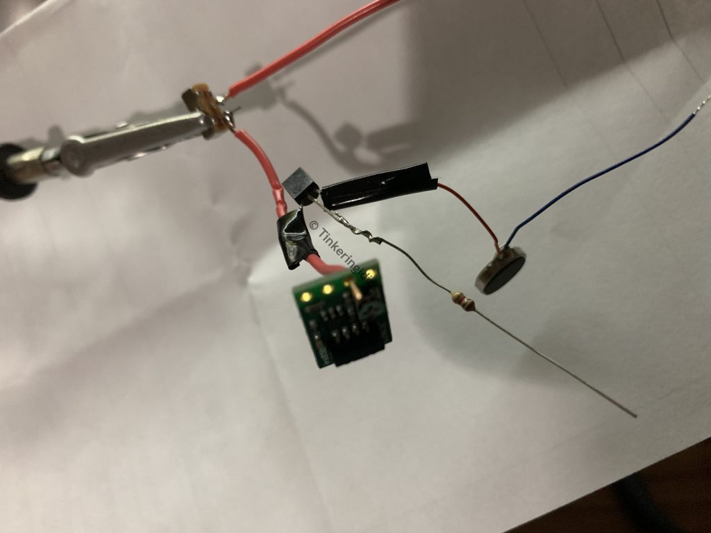
The resistor gets soldered in to the IR receiver’s OUT pin (the center one next to the VDD pin).

I next solder a short black wire to the the receiver’s GND pin.

This black wire connects to the motor’s blue wire.

The long red wire connects to the positive terminal on the battery holder. Mine has two of these on the ‘+’ side, and a negative terminal in the center on the ‘-‘ side.

For the final bit of soldering, I attach the black and blue solder joint to the battery’s negative terminal. It’s starting to look a bit like a rat’s nest at this point, but that will actually help it fit in the case.

With the circuit complete, I pack everything in to the case. The motor goes in the center circular section, the switch goes in its own hole, and the IR receiver slots in to the top. I pack the rest of the wiring in as nicely as I can.
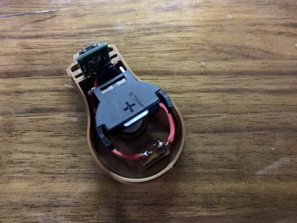
Then, as is proper for all small electronics products, I glob in some hot glue randomly to keep everything nice and secure. I’m not sure it counts as an electronics project if hot glue isn’t involved.
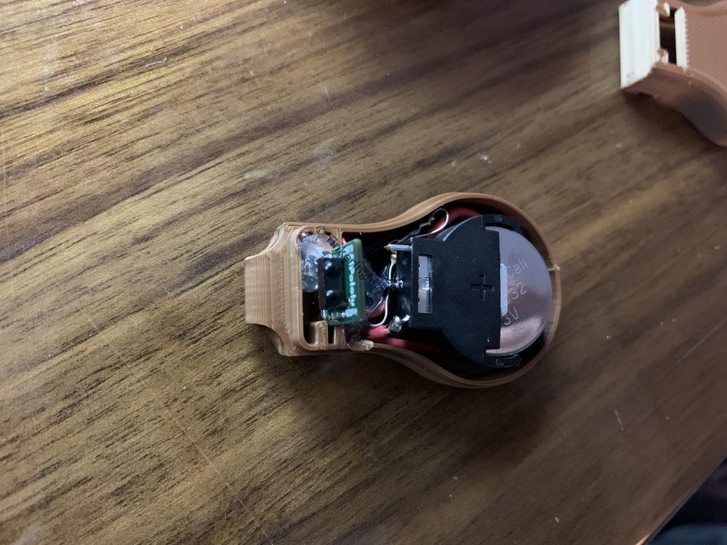
At this point, I can slot in a battery, pop on the top cover, and fire it up, but it’s a little over sensitive. There’s a small silver component on the bottom of the IR receiver (the emitter side) that needs covered to keep the sensor from going off randomly. The instructions from JPL state that a variety of things work here, but I’m using a tiny square of electrical tape, and it seems to do the job just fine. Or just use a case printed in black, which others say solves this problem.

And that’s that. A relatively quick (and fun) build for a simple, but useful little device. I made several for high-risk family members, and thus far they’re working very well. I wore one myself on a trip to the grocery store, and was shocked at how often it had to remind me to keep my hands off my face. Big thanks to NASA JPL for the design!

film
Hi there, I wish for to subscribe for this blog to take hottest updates, thus where can i do it please help. Lucia Itch Doersten
The Idiot
Hello and welcome! I’ve added a subscription form on the right side (or bottom, on mobile). I’ll keep you updated with all my latest posts!