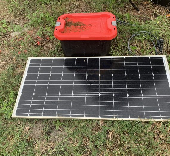
As I detailed in this post, I enjoy running my garden on solar power. There’s something gratifying about using the sun to power the automation systems that grow plants from, well, the sun.
I love my little solar generators, but they’ve got a few problems, primarily with how the load is handled:
- First, I used an inverter to convert 12v DC to 120v AC. This is a simple solution or a relatively simple problem (i.e. the internet not having a very good selection of 12v pumps at the time), but it’s pretty inefficient. I don’t need perfect efficiency, but I’m pretty sure I can do better than “terrible”, so it’s been irritating me for awhile.
- Second, it’s bulky. A big, boxy inverter, with a big power strip, and a couple of “how do these look identical to the ones we had in the 80’s” mechanical timers takes up a lot of room in the tote. A timer and pump connection shouldn’t be this big.
- Third, more components means more stuff that’ll break down. Every one that does means dead plants, so this is literally a matter of life and death. Better to keep it simple.
- Fourth (and most importantly), I don’t want to be done tinkering with this design yet, so while it ain’t broke, I’m gonna fix it anyway.
So, I’m making the whole thing run at 12v DC.
Doing more with less
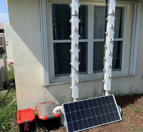
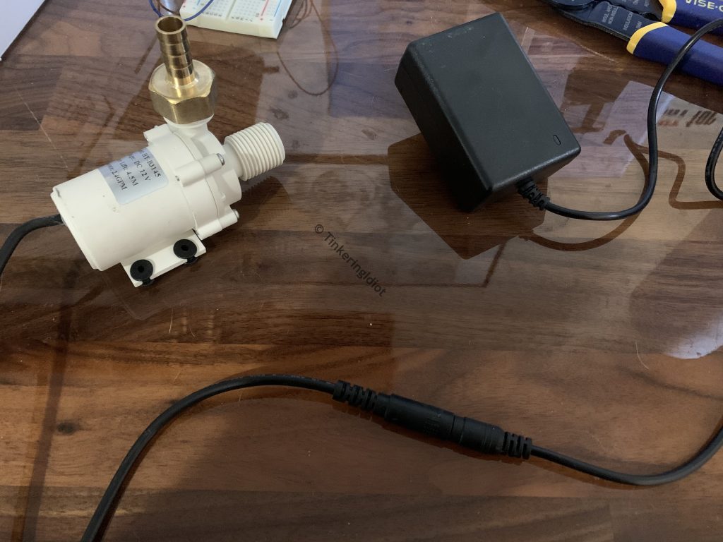
The generator I’m working on this time is for my strawberry tower. 12v DC isn’t going to power those 120v AC pumps I used before, and those pumps just aren’t up to the task. Every pump has a head height, which is how much vertical distance it can move water – as if it were pumping straight upward. Those 120v AC pumps can manage about 6 feet of vertical distance. Not good for 8 foot high strawberry towers.
The world of 12v pumps surprised me. Not only are there many more available than I was expecting, but they’re surprisingly powerful for very little money. I went with these HuiYu 2.4 GPM pumps (which aren’t available a few months later, but this Bayite 2.1 GPM is similar). These things have a head height significantly higher than comparably priced 120v AC pumps. Are 12v pumps just inherently more torquey? Maybe, I have no idea. I just know that I’m in love.
Timing is everything
Finding 12v timers isn’t difficult at all. They’re all over the place, sporting a wide variety of features and…well, OK, they’re all pretty much the same thing in different packages, but that’s just how 21st century manufacturing works. 18 working modes and 17 on/off cycles (like 640k of memory) ought to be enough for anyone.
Except when it’s not. My strawberries need to be watered every 15 minutes or so, all day long, which is way more than 17 on/off cycles. So, I need a bit more control over the programming. Realistically, can I make one of these off-the-shelf timers work if I actually read through the instructions? Probably, but why deny myself the pleasure of building something from scratch that no one needs?
Compelling components
Timers of the sort I need are pretty simple critters. It’s basically just a relay, with some sort of magic brain box to tell it when to open and close. Thankfully, the relay is easy – it’s really just a switch, and the “internet of things” revolution has those things all over the place. Since I’m controlling two pumps, I chose this 2-channel relay board from Youngneer. At 250v AC and 10A, it’ll handle far more power than my little pumps could ever draw, but the important part is that it’s activated by 5v. Why does that matter? Because an Arduino (a small computer) uses 5v on its general purpose input/output (GPIO) pins.
Which means, of course, that I’m using an Arduino to drive the relays. If you’re not familiar with Arduino, it’s a series of very small, low-powered computers, good for automating simple tasks like running pumps on a schedule. Specifically, I’m using an Arduino Nano, which is an even smaller (slightly larger than a quarter) version of an Arduino. More specifically, I’m using an off-brand Arduino clone, because the fine folks at Arduino released their hardware designs to the world for free.
Wielding power responsibly
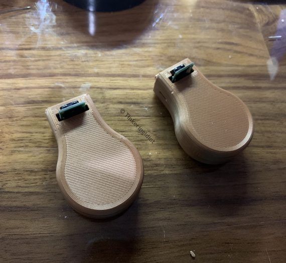
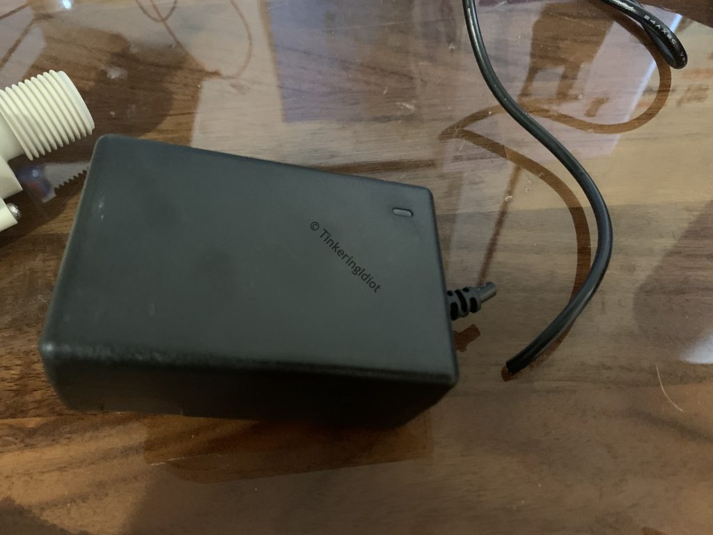
Once I’ve got all the pieces, it’s time to cobble them together and hope the whole thing doesn’t explode. To start with, my pumps, 12v though they may be, came with a power adapter attached.
I clip them as close to the adapter block as possible, to give myself plenty of cable to work with. In the end, the pump will sit in the strawberry tower’s reservoir, while the timer will be in another tote – I want enough cable to reach between the two.
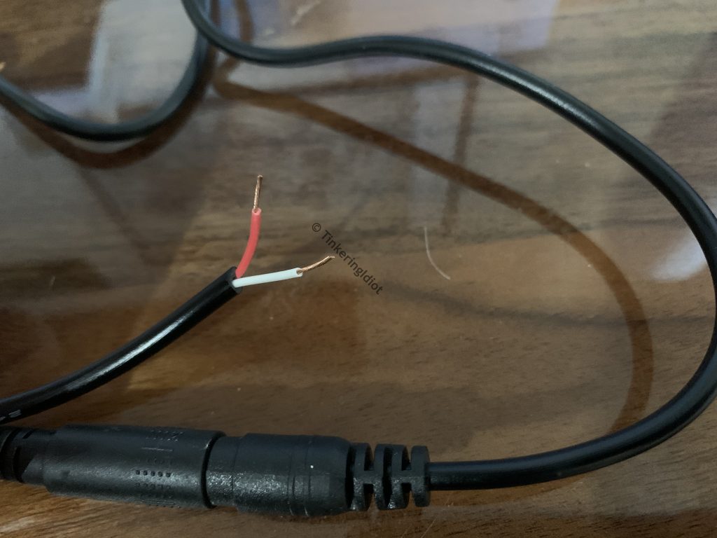
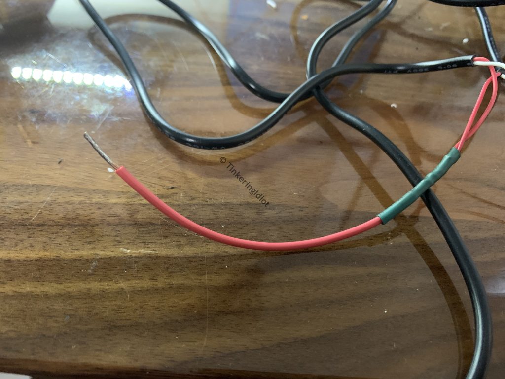
I strip the wires, and then test them to figure out, for sure and for certain, which is positive and which is negative. This is somewhat important, since if I wire them in backward, the pump could also run backward. I don’t want that. In this case, the red wire is positive, and the white is negative. That should usually be the case, but it’s always worth testing to be sure.
I wrap the positive wires together, and attach a few inches of 18AWG wire using the world’s ugliest splice knot and solder. I also tin the negative leads while I’m at it, since they’ll be clamped in the relays.
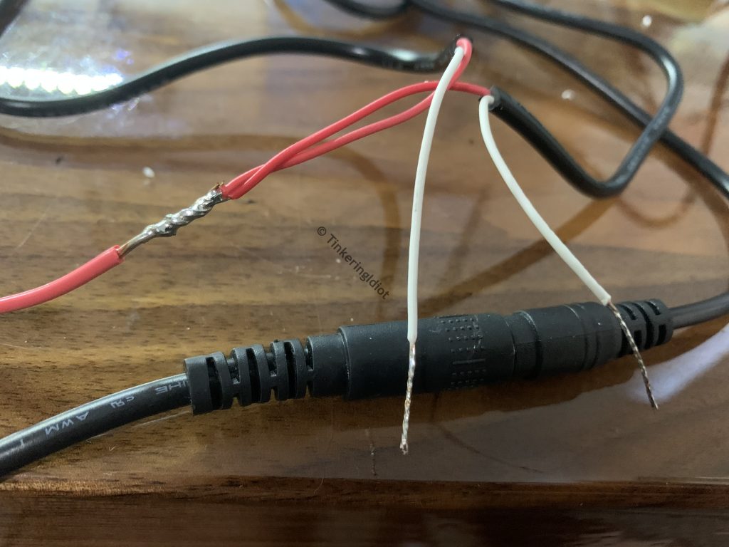
A little heat shrink tube and a tinned end of the positive wire completes this leg.
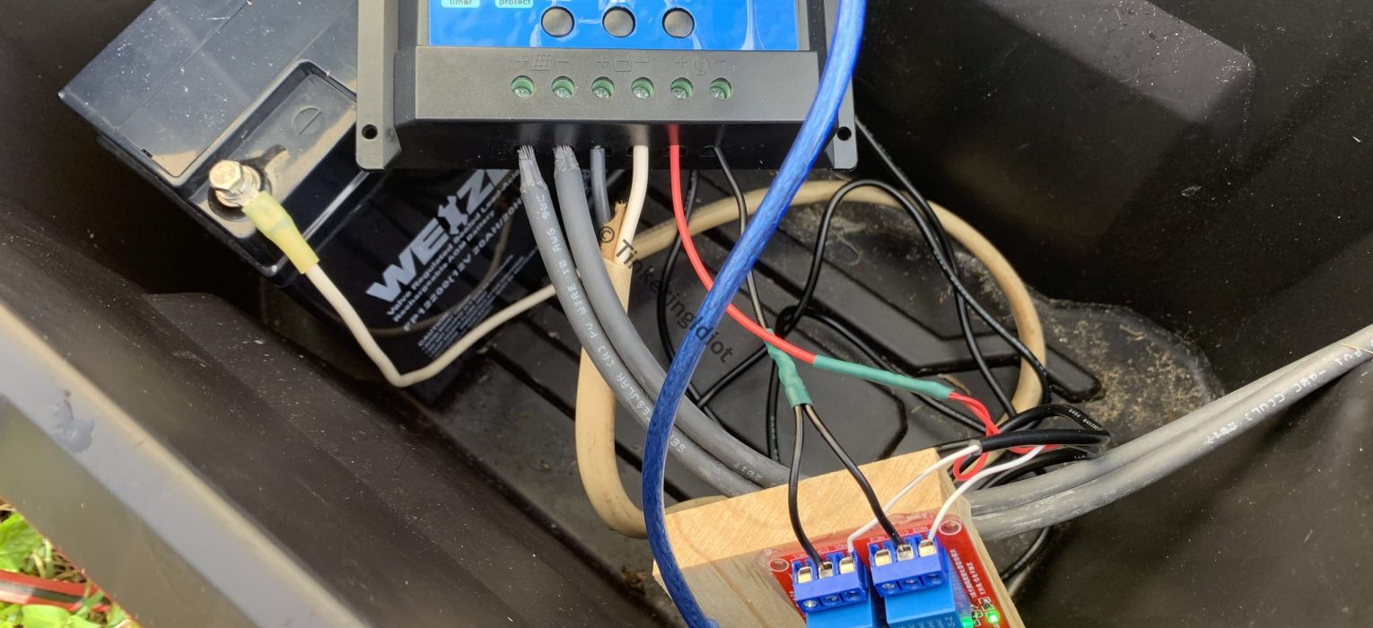
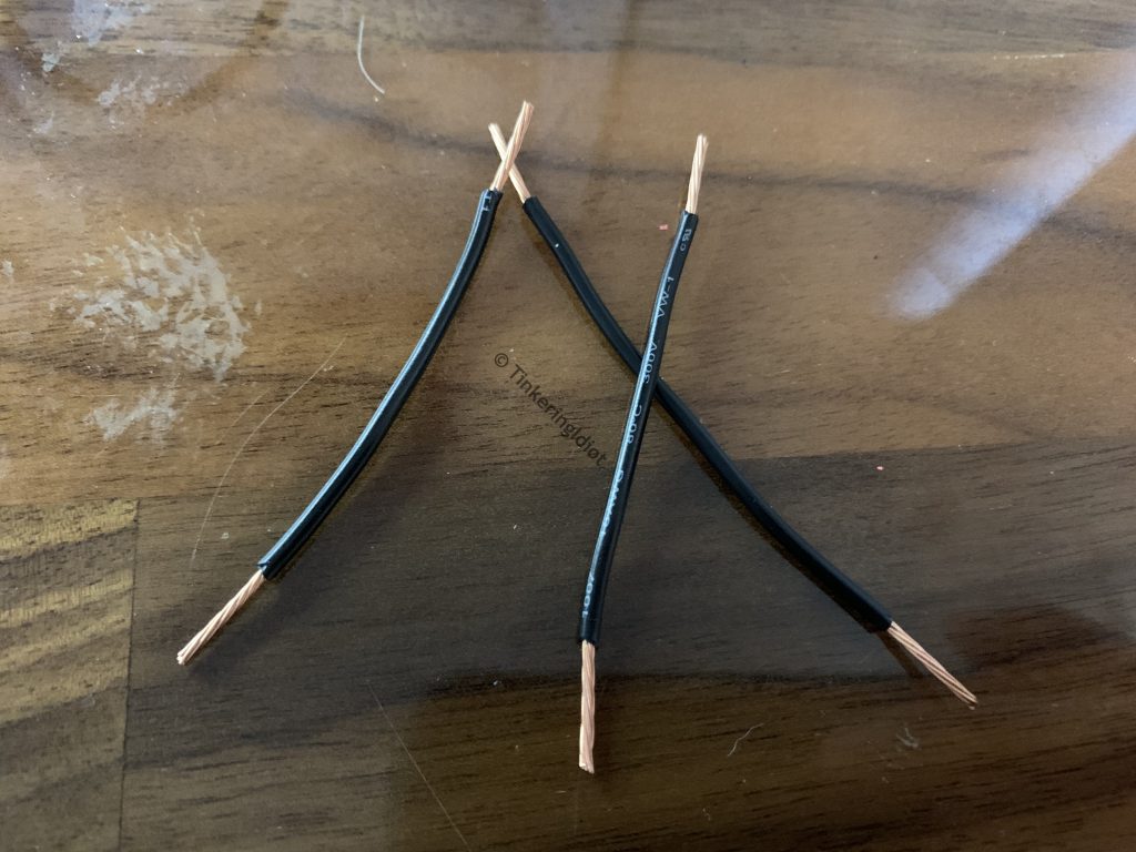
I’ll also need a negative leg to connect the other side of the relays to the negative terminal on the charge controller. Since there are two relays and only one terminal, I make a Y-shaped jumper using the same splice-and-solder as on the positive leg.
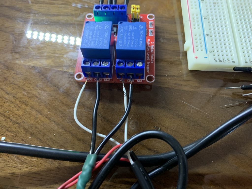
With the pump wiring ready, I can connect them to the relays. Each relay has two side posts, marked NO (normally open) and NC (normally closed), and one center post marked COM (common). The COM post is simple enough, it just gets connected to the negative load terminal on the charge controller.
Normally-open and normally-closed refer to the state of the relay when it isn’t activated (i.e. “normal”). It’s helpful here to think of the relay as a regular switch, connecting and disconnecting the load. If the circuit is open (which is to say, not connected), the load is off, so the NO side of the relay makes it act like an on switch – the load is normally off, but when the relay activates, the circuit is closed and the load turns on. The NC side is the opposite – the load is normally on, and the relay shuts it off.
Since I don’t want the pumps running all the time, I connect the negative wire from each pump to the NO side of each relay.
Flipping switches
With the relays hooked up, I need to turn them on an off on a schedule. This is where the Arduino comes in.
The Arduino is a computer, and as such, requires a little bit of programming. For some projects that might be a little intimidating, but trust me, in this case it’s not. This is the sum total of the code that needs written:
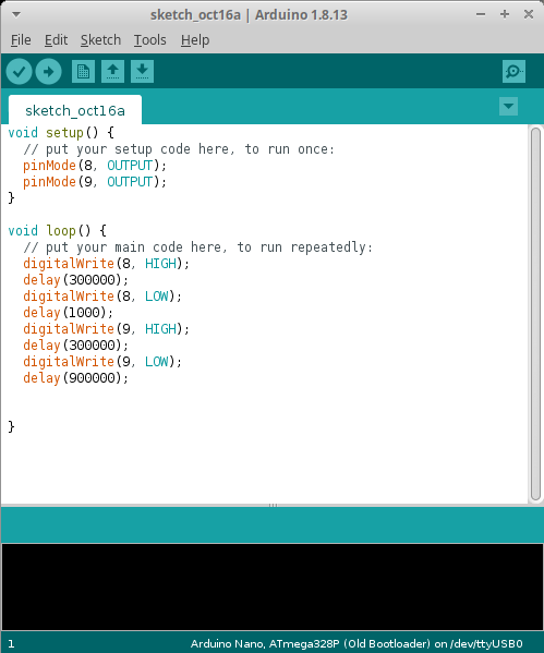
The code is quite simple. In the setup block at the top (which runs once as the Arduino boots up), the pinMode function just sets a pin (8 and 9 in this case) to OUTPUT mode – it tells the Arduino that I’m going to output a 5v signal on those pins. The loop function runs over and over forever, hence the name. digitalWrite(8, HIGH) sends 5v (which, remember, will activate the relay) down pin 8, and digitalWrite(8, LOW) stops it. digitalWrite does the same for pin 9. The delay function tells the Arduino to just wait for a number of milliseconds (ms, thousandths of a second). So, the order of operations here is like this:
- Turn on pin 8
- Wait 300,000 ms = 300 seconds = 5 minutes
- Turn off pin 8
- Wait 1,000 ms = 1 second
- Turn on pin 9
- Wait 300,000 ms = 300 seconds = 5 minutes
- Turn off pin 9
- Wait 900,000 ms = 900 seconds = 15 minutes
- Do it all over again
Pin 8 will activate one relay, and pin 9 the other, so all I’m doing with this code is turning one pump on for 5 minutes, then the other, then waiting 15 minutes.
After uploading the code to the Arduino (for this board, use the “ATmega328p (Old Bootloader)” processor setting), the brain box is ready to go.
Brain wiring
Now it’s just a matter of connecting the Arduino to the relays. Since the Arduino has pins, the relay board has clamps, and I’m only working with 5v DC, I sacrifice a few breadboard jumpers for the cause by stripping one end.
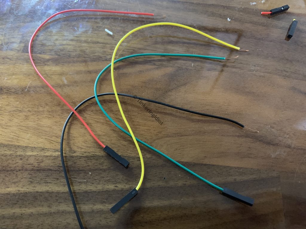
The yellow wire connects the Arduino’s pin D8 to IN2 on the relay input, and the green connects D9 to IN1 (I suppose I got that sort of backward, but it doesn’t really matter).
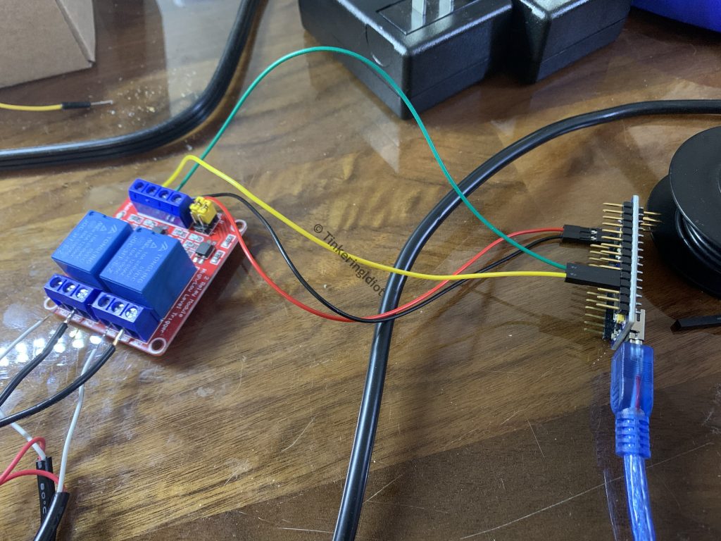
The relay board also requires power via the DC+ and DC- ports. If I were doing this correctly, I’d probably use a micro-USB breakout or 12v from the charge controller to power both the Arduino and the relay board. But then, if I were prone to strict correctness, I probably wouldn’t have to call myself an idiot on the internet.
The Arduino Nano has a couple of GND pins, which will serve as DC- on the relay board, so that’s where I connect the black wire. Interestingly, while tinkering with a meter I noticed that the Arduino’s VIN pin has +5v DC on it when powered via USB. VIN in electronics terms normally means “power goes in here”, not “power comes out of here”, and the Arduino documentation backs this up. But, the meter doesn’t lie, and using the red wire to connect the VIN pin to the relay’s DC+ does indeed power up the relay board. Maybe I’m reading the documentation wrong (this has happened before), or maybe this off-brand Arduino isn’t quite built to spec (this has also happened before). I’m not sure why it works, but it does.
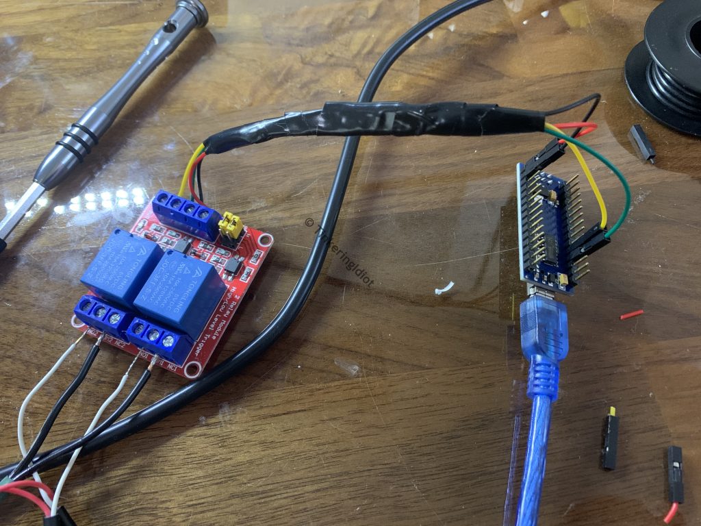
In a fit of cable-management gusto, I wrap the leads with electrical tape.
Then, to bring everything together in a single unit, I mount the Arduino and relay board on a space-age carbon composite substrate using a high-temperature potting solution.
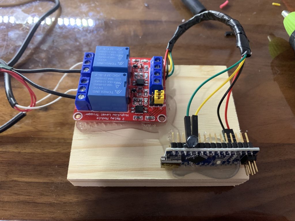
Yeah, scrap wood and hot glue. The height of hold my beer and watch this engineering.
With the timer complete, I install it and the new pumps as the load on the solar charge controller, and, wonder of wonders, it works. It’s not my prettiest project ever (and I probably should have used…any resistors at all), but the plants are getting watered, so I’m calling it a win.